Chapter 1 Procedural Modeling Beginning with Unity
1.1 Introduction
Procedural Modeling is a technique for building 3D models using rules. Modeling generally refers to using modeling software such as Blender or 3ds Max to manually operate to obtain the target shape while moving the vertices and line segments. In contrast, the approach of writing rules and obtaining shape as a result of a series of automated processes is called procedural modeling.
Procedural modeling is applied in various fields. For example, in games, there are examples of being used for terrain generation, plant modeling, city construction, etc. By using this technology, each time you play, you will be staged. Content design such as changing the structure becomes possible.
Also, in the fields of architecture and product design, the method of procedurally designing shapes using Grasshopper * 2 , which is a CAD software plug-in called Rhinoceros * 1 , is being actively used.
With procedural modeling, you can:
- Can create parametric structures
- Flexible models can be incorporated into the content
1.1.1 Can create parametric structures
A parametric structure is a structure in which the elements of the structure can be deformed according to a certain parameter. For example, in the case of a sphere model, the radius representing the size and the smoothness of the sphere are calculated. You can define parameters such as the number of segments to represent, and by changing those values, you can obtain a sphere with the desired size and smoothness.
Once you have implemented a program that defines a parametric structure, you can get a model with a specific structure in various situations, which is convenient.
1.1.2 Flexible models can be incorporated into content
As mentioned above, in fields such as games, there are many examples where procedural modeling is used to generate terrain and trees, and it is generated in real time in the content instead of incorporating what was once written as a model. Sometimes. Using procedural modeling techniques for real-time content, for example, you can create a tree that grows toward the sun at any position, or build a city where buildings line up from the clicked position. It can be realized.
In addition, incorporating models of various patterns into the content will increase the data size, but if you use procedural modeling to increase the variation of the model, you can reduce the data size.
If you learn procedural modeling techniques and build models programmatically, you will be able to develop your own modeling tools.
1.2 Model representation in Unity
In Unity, the geometry data that represents the shape of the model is managed by the Mesh class.
The shape of the model consists of triangles arranged in 3D space, and one triangle is defined by three vertices. The official Unity documentation explains how to manage the vertex and triangle data of the model in the Mesh class as follows.
In the Mesh class, all vertices are stored in one array, and each triangle is specified by three integers that are the indexes of the vertex array. The triangles are further collected as an array of integers. This integer is grouped every three from the beginning of the array, so elements 0, 1, and 2 define the first triangle, followed by the second triangles 3, 4, 5. * 3
The model has uv coordinates that represent the coordinates on the texture required for texture mapping to correspond to each vertex, and normal vectors (also called normal) required to calculate the influence of the light source during lighting. Can be included).
Sample repository
In this chapter, the following Assets / ProceduralModeling in the https://github.com/IndieVisualLab/UnityGraphicsProgramming repository are prepared as sample programs.
Since model generation by C # script is the main content of the explanation, we will proceed with the explanation while referring to the C # script under Assets / ProceduralModeling / Scripts.
Execution environment
The sample code in this chapter has been confirmed to work with Unity 5.0 and above.
1.2.1 Quad
Taking Quad, which is a basic model, as an example, we will explain how to build a model programmatically. Quad is a square model that combines two triangles consisting of four vertices, which is provided by default as Primitive Mesh in Unity, but since it is the most basic shape, it is an example to understand the structure of the model. Useful.

Figure 1.1: Quad model structure Black circles represent the vertices of the model, and the numbers 0 to 3 in the black circles indicate the index of the vertices. Triangles specified in the order of 1,2, lower left is triangles specified in the order of 2,3,0)
Sample program Quad.cs
First, create an instance of the Mesh class.
// Create an instance of Mesh
var mesh = new Mesh ();
Next, generate a Vector3 array that represents the four vertices located at the four corners of the Quad. Also, prepare the uv coordinate and normal data so that they correspond to each of the four vertices.
// Find half the length so that the width and height of the Quad are the length of size respectively.
var hsize = size * 0.5f;

// Quad vertex data
var vertices = new Vector3[] {
    new Vector3 (-hsize, hsize, 0f), // Upper left position of the first vertex Quad
    new Vector3 (hsize, hsize, 0f), // Upper right position of the second vertex Quad
    new Vector3 (hsize, -hsize, 0f), // Lower right position of the third vertex Quad
    new Vector3 (-hsize, -hsize, 0f) // Lower left position of the 4th vertex Quad
};

// Quad uv coordinate data
var uv = new Vector2[] {
    new Vector2 (0f, 0f), // uv coordinates of the first vertex
    new Vector2 (1f, 0f), // uv coordinates of the second vertex
    new Vector2 (1f, 1f), // uv coordinates of the third vertex
    new Vector2 (0f, 1f) // uv coordinates of the 4th vertex
};

// Quad normal data
var normals = new Vector3[] {
    new Vector3 (0f, 0f, -1f), // normal of the first vertex
    new Vector3 (0f, 0f, -1f), // Normal of the second vertex
    new Vector3 (0f, 0f, -1f), // normal of the third vertex
    new Vector3 (0f, 0f, -1f) // Normal of the 4th vertex
};
Next, generate triangular data that represents the faces of the model. The triangle data is specified by an array of integers, and each integer corresponds to the index of the vertex array.
// Quad face data Recognize as one face (triangle) by arranging three indexes of vertices
var triangles = new int[] {
    0, 1, 2, // 1st triangle
    2, 3, 0 // Second triangle
};
Set the last generated data to the Mesh instance.
mesh.vertices = vertices;
mesh.uv = uv;
mesh.normals = normals;
mesh.triangles = triangles;

// Calculate the boundary area occupied by Mesh (required for culling)
mesh.RecalculateBounds();

return mesh;
1.2.2 ProceduralModelingBase
The sample code used in this chapter uses a base class called ProceduralModelingBase. In the inherited class of this class, every time you change a model parameter (for example, size that represents width and height in Quad), a new Mesh instance is created and applied to MeshFilter to check the change result immediately. I can. (This function is realized by using the Editor script. ProceduralModelingEditor.cs)
You can also visualize the UV coordinates and normal direction of the model by changing the enum type parameter called ProceduralModelingMaterial.
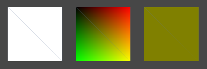
Figure 1.2: From the left, the model to which ProcedureModelingMaterial.Standard, ProcedureModelingMaterial.UV, and ProcedureModelingMaterial.Normal are applied.
1.3 Primitive shape
Now that you understand the structure of your model, let's create some primitive shapes.
1.3.1 Plane
Plane is shaped like a grid of Quads.
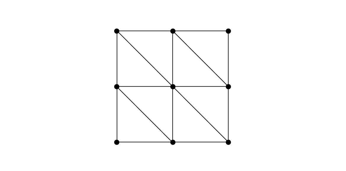
Figure 1.3: Plane model
Determine the number of rows and columns of the grid, place vertices at the intersections of each grid, build a Quad to fill each cell of the grid, and combine them to generate one Plane model.
In the sample program Plane.cs, the number of vertices arranged vertically in the Plane, heightSegments, the number of vertices arranged horizontally widthSegments, and the parameters of vertical length height and horizontal length width are prepared. Each parameter affects the shape of the Plane as shown in the following figure.
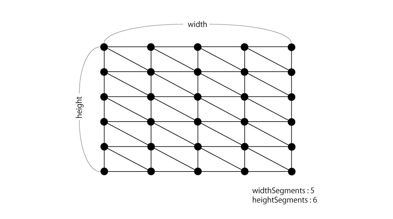
Figure 1.4: Plane parameters
Sample program Plane.cs
First, we will generate vertex data to be placed at the intersections of the grid.
var vertices = new List<Vector3>();
var uv = new List<Vector2>();
var normals = new List<Vector3>();

// The reciprocal of the number of matrices to calculate the percentage of vertices on the grid (0.0 to 1.0)
var winv = 1f / (widthSegments - 1);
var hinv = 1f / (heightSegments - 1);

for(int y = 0; y < heightSegments; y++) {
    // Row position percentage (0.0 ~ 1.0)
    var ry = y * hinv;

    for(int x = 0; x < widthSegments; x++) {
        // Percentage of column positions (0.0 ~ 1.0)
        var rx = x * winv;

        vertices.Add(new Vector3(
            (rx - 0.5f) * width,
            0f,
            (0.5f - ry) * height
        ));
        uv.Add(new Vector2(rx, ry));
        normals.Add(new Vector3(0f, 1f, 0f));
    }
}
Next, regarding triangle data, the vertex index set for each triangle is referenced as shown below in the loop that follows the rows and columns.
var triangles = new List<int>();

for(int y = 0; y < heightSegments - 1; y++) {
    for(int x = 0; x < widthSegments - 1; x++) {
        int index = y * widthSegments + x;
        var a = index;
        var b = index + 1;
        var c = index + 1 + widthSegments;
        var d = index + widthSegments;

        triangles.Add(a);
        triangles.Add(b);
        triangles.Add(c);

        triangles.Add(c);
        triangles.Add(d);
        triangles.Add(a);
    }
}
ParametricPlaneBase
The height (y coordinate) value of each vertex of Plane was set to 0, but by manipulating this height, it is not just a horizontal surface, but an uneven terrain or a shape like a small mountain. Can be obtained.
The ParametricPlaneBase class inherits from the Plane class and overrides the Build function that creates the mesh. First, generate the original Plane model, call the Depth (float u, float v) function to find the height by inputting the uv coordinates of each vertex, and reset the height to flexibly shape it. Transforms.
By implementing a class that inherits this ParametricPlaneBase class, you can generate a Plane model whose height changes depending on the vertices.
Sample program ParametricPlaneBase.cs
protected override Mesh Build() {
    // Generate the original Plane model
    var mesh = base.Build ();

    // Reset the height of the vertices of the Plane model
    var vertices = mesh.vertices;

    // The reciprocal of the number of matrices to calculate the percentage of vertices on the grid (0.0 to 1.0)
    var winv = 1f / (widthSegments - 1);
    var hinv = 1f / (heightSegments - 1);

    for(int y = 0; y < heightSegments; y++) {
        // Row position percentage (0.0 ~ 1.0)
        var ry = y * hinv;
        for(int x = 0; x < widthSegments; x++) {
            // Percentage of column positions (0.0 ~ 1.0)
            var rx = x * winv;

            int index = y * widthSegments + x;
            vertices[index].y = Depth(rx, ry);
        }
    }

    // Reset the vertex position
    mesh.vertices = vertices;
    mesh.RecalculateBounds();

    // Automatically calculate normal direction
    mesh.RecalculateNormals();

    return mesh;
}
In the sample scene ParametricPlane.scene, GameObject using the class (MountainPlane, TerrainPlane class) that inherits this ParametricPlaneBase is placed. Try changing each parameter and see how the shape changes.
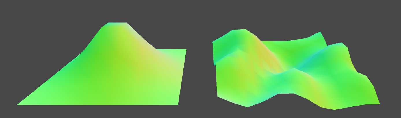
Figure 1.5: ParametricPlane.scene Model generated by the MountainPlane class on the left and the TerrainPlane class on the right
1.3.2 Cylinder
The Cylinder is a cylindrical model that looks like the following figure.
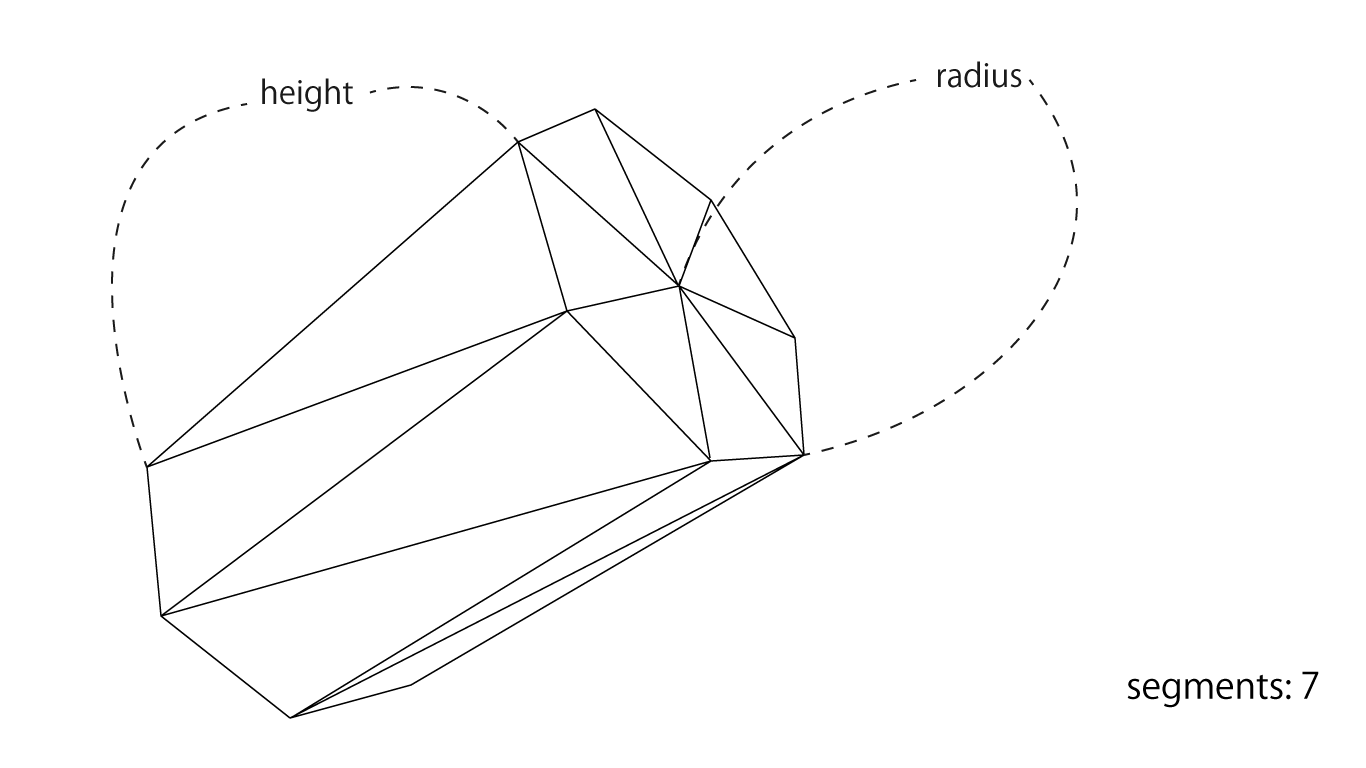
Figure 1.6: Structure of Cylinder
The smoothness of the cylindrical circle can be controlled by the segments, and the vertical length and thickness can be controlled by the height and radius parameters, respectively. As shown in the example above, if you specify 7 for segments, the cylinder will look like a regular heptagon stretched vertically, and the larger the value of segments, the closer it will be to a circle.
Vertices evenly aligned along the circumference
The vertices of the Cylinder should be evenly aligned around the circle located at the end of the cylinder.
Use trigonometric functions (Mathf.Sin, Mathf.Cos) to place evenly aligned vertices along the circumference. The details of trigonometric functions are omitted here, but these functions can be used to obtain the position on the circumference based on the angle.
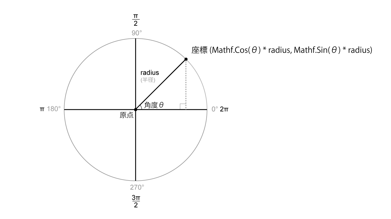
Figure 1.7: Obtaining the position of a point on the circumference from a trigonometric function
As shown in this figure, the points located on the circle of radius radius from the angle θ (theta) are acquired by (x, y) = (Mathf.Cos (θ) * radius, Mathf.Sin (θ) * radius). can do.
Based on this, perform the following processing to obtain the vertex positions of segments evenly arranged on the circumference of the radius radius.
for (int i = 0; i < segments; i++) {
    // 0.0 ~ 1.0
    float ratio = (float)i / (segments - 1);

    // Convert [0.0 ~ 1.0] to [0.0 ~ 2π]
    float rad = ratio * PI2;

    // Get a position on the circumference
    float cos = Mathf.Cos(rad), sin = Mathf.Sin(rad);
    float x = cos * radius, y = sin * radius;
}
In Cylinder modeling, vertices are evenly placed along the circumference of the end of the cylinder, and the vertices are joined together to form a side surface. For each side, just as you would build a Quad, take two corresponding vertices from the top and bottom and place the triangles facing each other to build one side, a rectangle. The sides of the Cylinder can be imagined as the Quads arranged along a circle.
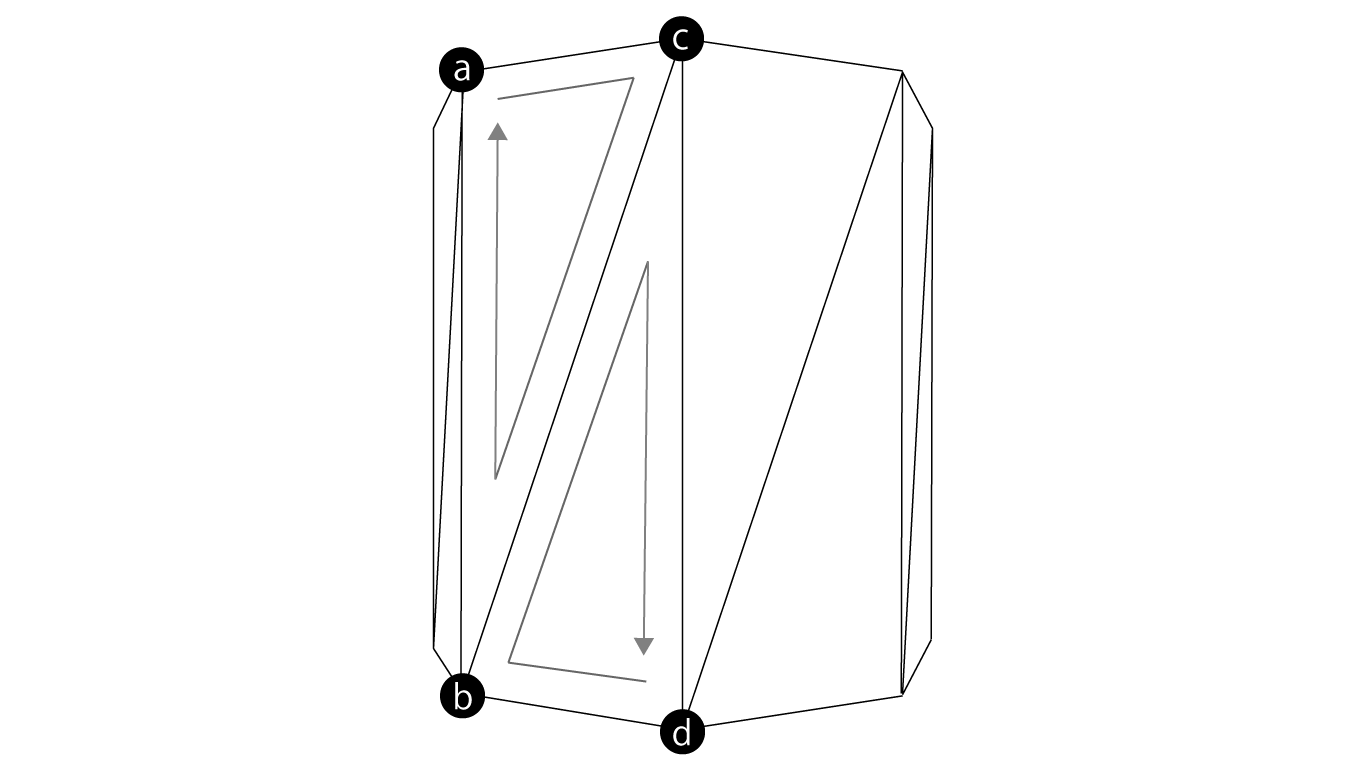
Figure 1.8: Modeling the sides of a cylinder Black circles are evenly distributed vertices along the circumference at the edges a to d in the vertices are index variables assigned to the vertices when constructing a triangle in the Cylinder.cs program.
Sample program Cylinder.cs
First of all, we will build the side, but in the Cylinder class, we have prepared a function GenerateCap to generate the data of the vertices arranged around the circumference located at the upper end and the lower end.
var vertices = new List<Vector3>();
var normals = new List<Vector3>();
var uvs = new List<Vector2>();
var triangles = new List<int>();

// Top height and bottom height
float top = height * 0.5f, bottom = -height * 0.5f;

// Generate vertex data that makes up the side
GenerateCap(segments + 1, top, bottom, radius, vertices, uvs, normals, true);

// To refer to the vertices on the circle when constructing the side triangles
// Divine for index to go around the circle
var len = (segments + 1) * 2;

// Build the sides by connecting the top and bottom
for (int i = 0; i < segments + 1; i++) {
    int idx = i * 2;
    int a = idx, b = idx + 1, c = (idx + 2) % len, d = (idx + 3) % len;
    triangles.Add(a);
    triangles.Add(c);
    triangles.Add(b);

    triangles.Add(d);
    triangles.Add(b);
    triangles.Add(c);
}
In the GenerateCap function, the vertex and normal data are set in the variable passed as List type.
void GenerateCap(
    int segments,
    float top,
    float bottom,
    float radius,
    List<Vector3> vertices,
    List<Vector2> uvs,
    List<Vector3> normals,
    bool side
) {
    for (int i = 0; i < segments; i++) {
        // 0.0 ~ 1.0
        float ratio = (float)i / (segments - 1);

        // 0.0 ~ 2π
        float rad = ratio * PI2;

        // Place vertices evenly at the top and bottom along the circumference
        float cos = Mathf.Cos(rad), sin = Mathf.Sin(rad);
        float x = cos * radius, z = sin * radius;
        Vector3 tp = new Vector3(x, top, z), bp = new Vector3(x, bottom, z);

        // upper end
        vertices.Add(tp);
        uvs.Add(new Vector2(ratio, 1f));

        // Bottom edge
        vertices.Add(bp);
        uvs.Add(new Vector2(ratio, 0f));

        if(side) {
            // Normal to the outside of the side
            var normal = new Vector3(cos, 0f, sin);
            normals.Add(normal);
            normals.Add(normal);
        } else {
            normals.Add (new Vector3 (0f, 1f, 0f)); // Normals pointing up the lid
            normals.Add (new Vector3 (0f, -1f, 0f)); // Normals pointing down the lid
        }
    }
}
In the Cylinder class, you can set with the openEnded flag whether to make the model with the top and bottom closed. If you want to close the top and bottom, form a circular "lid" and plug the ends.
The vertices that make up the surface of the lid do not use the vertices that make up the side, but create a new vertex at the same position as the side. This is to separate the normals on the sides and the lid for natural lighting. (When constructing the vertex data of the side, specify true in the side variable of the argument of GenerateCap, and when constructing the lid, specify false so that the appropriate normal direction is set.)
If the side and lid share the same vertex, the side and lid will refer to the same normal, which makes lighting unnatural.
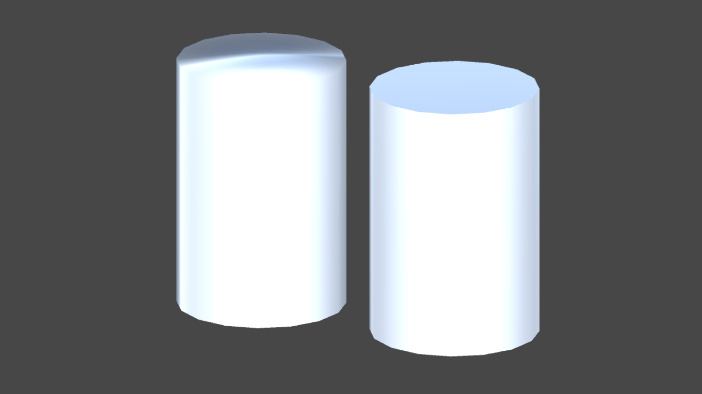
Figure 1.9: When the side of Cylinder and the top of the lid are shared (left: BadCylinder.cs) and when another vertex is prepared as in the sample program (right: Cylinder.cs) The lighting on the left becomes unnatural. ing
To model a circular lid, prepare vertices that are evenly arranged on the circumference (generated from the GenerateCap function) and vertices that are located in the middle of the circle, and the vertices along the circumference from the middle vertex. Join together to form a circular lid by building a triangle that resembles an evenly divided pizza.
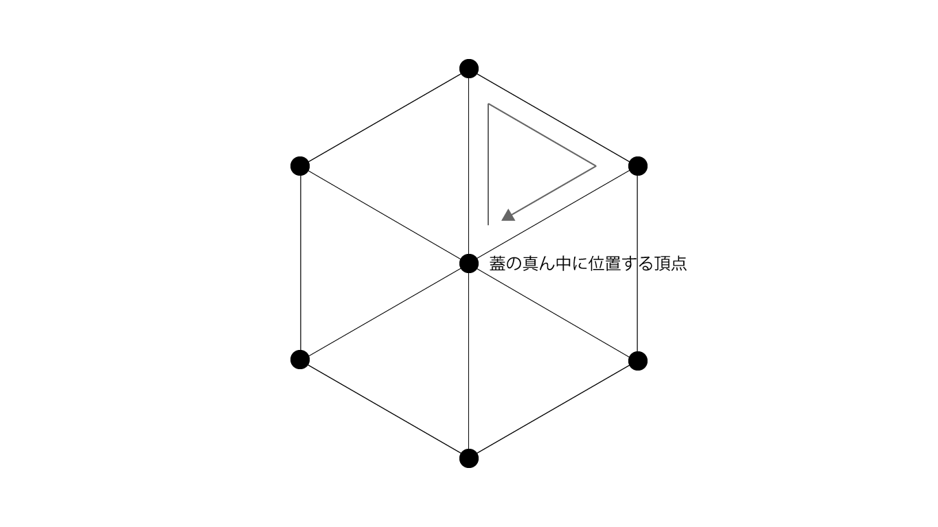
Figure 1.10: Cylinder lid modeling example with segments parameter of 6.
// Generate top and bottom lids
if(openEnded) {
    // Add new vertices for lid model, not shared with sides, to use different normals when lighting
    GenerateCap(
        segments + 1,
        top,
        bottom,
        radius,
        vertices,
        uvs,
        normals,
        false
    );

    // The apex in the middle of the top lid
    vertices.Add(new Vector3(0f, top, 0f));
    uvs.Add(new Vector2(0.5f, 1f));
    normals.Add(new Vector3(0f, 1f, 0f));

    // The apex in the middle of the bottom lid
    vertices.Add(new Vector3(0f, bottom, 0f)); // bottom
    uvs.Add(new Vector2(0.5f, 0f));
    normals.Add(new Vector3(0f, -1f, 0f));

    var it = vertices.Count - 2;
    var ib = vertices.Count - 1;

    // offset to avoid referencing the vertex index for the side
    var offset = len;

    // Top lid surface
    for (int i = 0; i < len; i += 2) {
        triangles.Add(it);
        triangles.Add((i + 2) % len + offset);
        triangles.Add(i + offset);
    }

    // Bottom lid surface
    for (int i = 1; i < len; i += 2) {
        triangles.Add(ib);
        triangles.Add(i + offset);
        triangles.Add((i + 2) % len + offset);
    }
}
1.3.3 Tubular
Tubular is a tubular model that looks like the following figure.
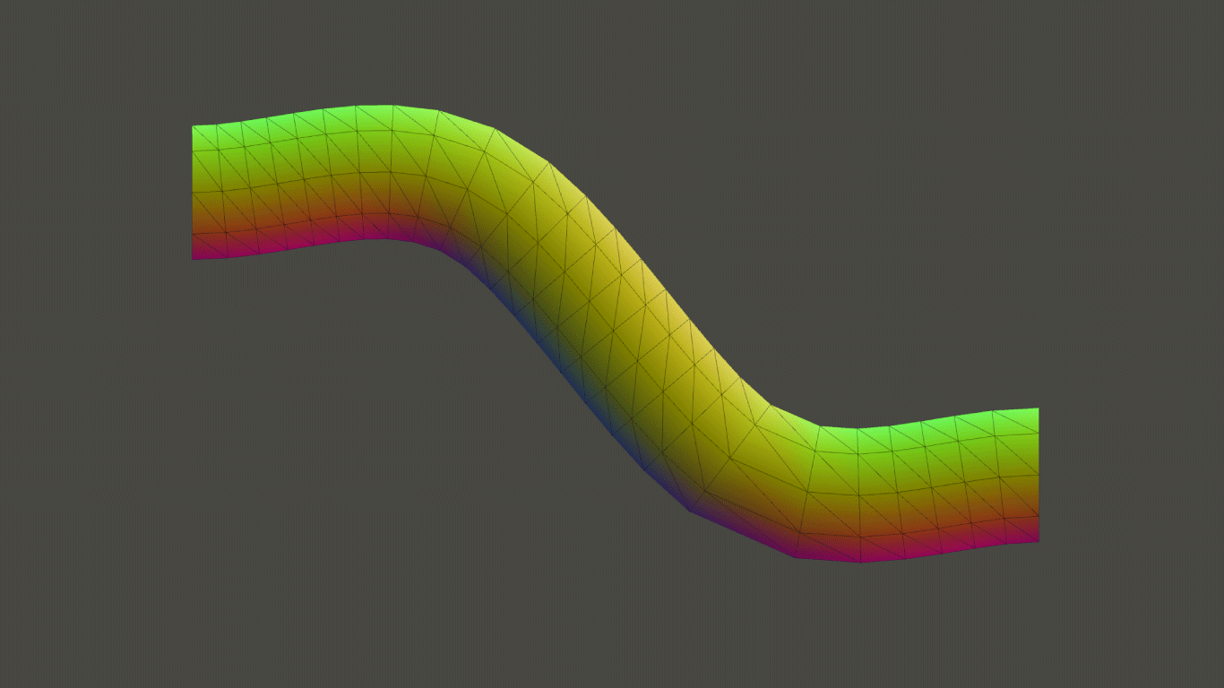
Figure 1.11: Tubular model
The Cylinder model has a straight cylindrical shape, while the Tubular has a curved, untwisted cylinder. In the example of the tree model described later, one branch is represented by Tubular, and a method of constructing one tree by combining them is adopted, but Tubular is used in situations where a tubular shape that bends smoothly is required. I will play an active part.
Cylindrical structure
The structure of the tubular model is as shown in the following figure.
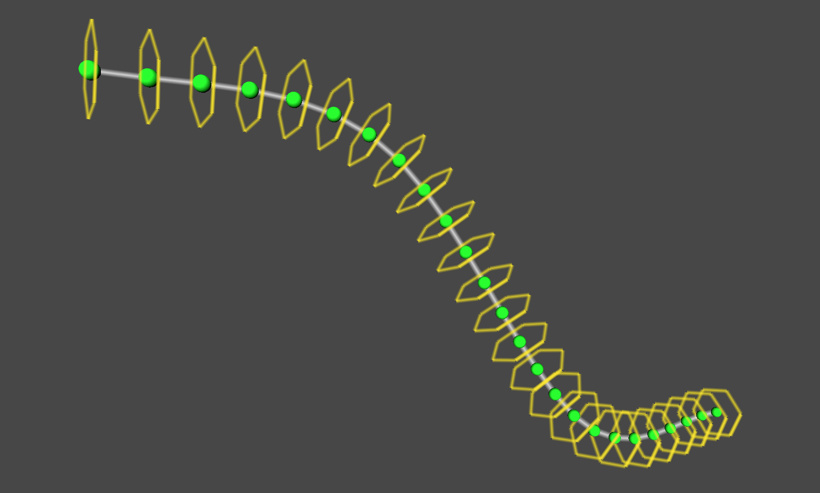
Figure 1.12: Cylindrical structure Tubular visualizes the points that divide the curve along with a sphere and the nodes that make up the sides with a hexagon.
Divide the curve, build sides for each node separated by the division points, and combine them to generate one Tubular model.
The sides of each node are similar to the sides of a cylinder, with the top and bottom vertices of the sides evenly arranged along a circle, and the cylinders are connected along a curve to build them together. You can think of things as Tubular types.
About curves
In the sample program, the base class CurveBase that represents a curve is prepared. Various algorithms have been devised for drawing curves in three-dimensional space, and it is necessary to select an easy-to-use method according to the application. In the sample program, the class CatmullRomCurve, which inherits the CurveBase class, is used.
I will omit the details here, but CatmullRomCurve has the feature of forming a curve while interpolating between points so that it passes through all the passed control points, and it is easy to use because you can specify the points you want to pass through the curve. Has a good reputation for its goodness.
The CurveBase class that represents a curve provides GetPointAt (float) and GetTangentAt (float) functions to obtain the position and slope (tangent vector) of a point on the curve, and specify a value of [0.0 to 1.0] as an argument. By doing so, you can get the position and slope of the point between the start point (0.0) and the end point (1.0).
Frenet frame
To create a twist-free cylinder along a curve, three orthogonal vectors "tangent vector, normal vector, binormal vector" that change smoothly along the curve You will need an array. The tangent vector is a unit vector that represents the slope at one point on the curve, and the normal vector and the normal vector are obtained as vectors that are orthogonal to each other.
With these orthogonal vectors, you can get "coordinates on the circumference orthogonal to the curve" at a point on the curve.
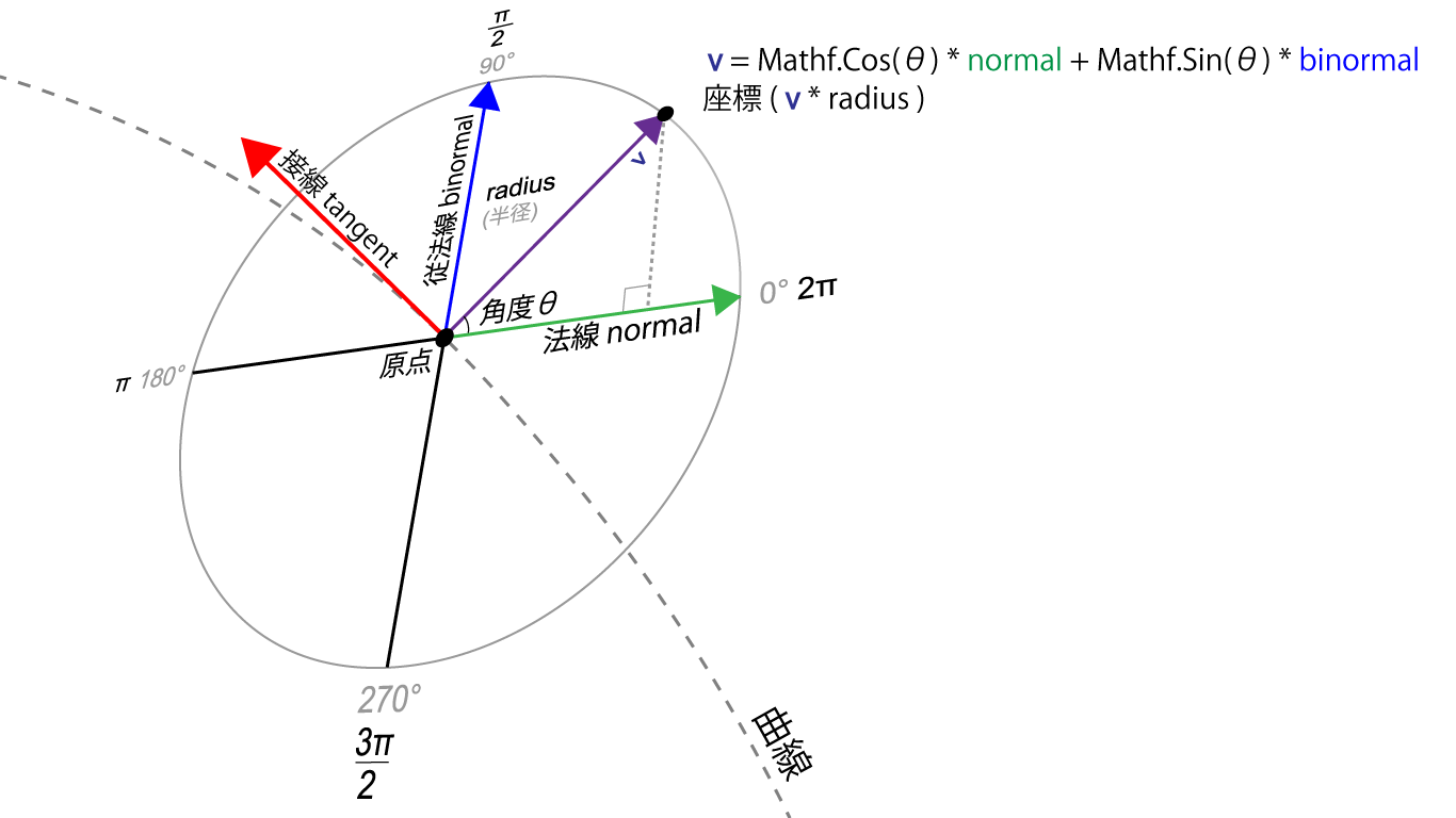
Figure 1.13: Find the unit vector (v) that points to the coordinates on the circumference from the normal and binormal. Multiply this unit vector (v) by the radius radius to make it orthogonal to the curve. You can get the coordinates on the circumference of the radius radius
A set of three orthogonal vectors at a point on this curve is called a Frenet frame.
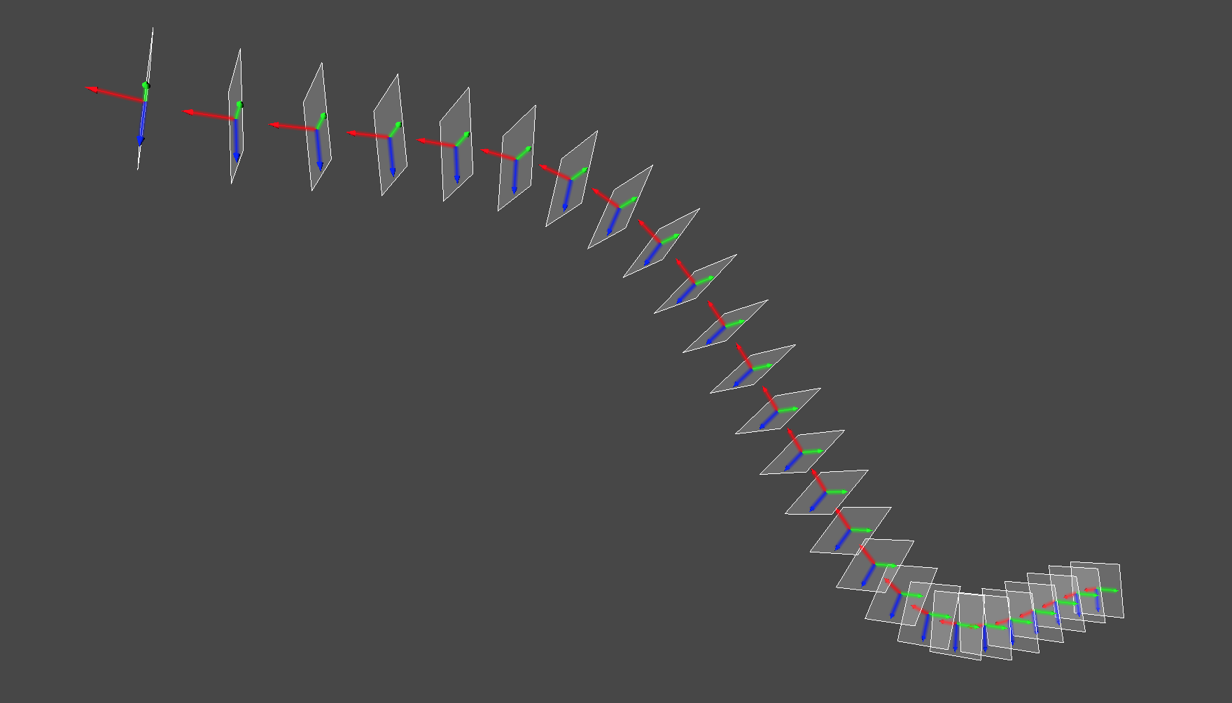
Figure 1.14: Visualization of the Frenet frame array that makes up Tubular The frame represents one Frenet frame, and the three arrows indicate the tangent vector, the normal vector, and the binormal vector.
Tubular modeling is performed by finding the vertex data for each clause based on the normals and binormals obtained from this Frenet frame, and connecting them together.
In the sample program, the CurveBase class has a function ComputeFrenetFrames to generate this Frenet frame array.
Sample program Tubular.cs
The Tubular class has a CatmullRomCurve class that represents a curve, and forms a cylinder along the curve drawn by this CatmullRomCurve.
The CatmullRomCurve class requires four or more control points, and when you manipulate the control points, the shape of the curve changes, and the shape of the Tubular model changes accordingly.
var vertices = new List<Vector3>();
var normals = new List<Vector3>();
var tangents = new List<Vector4>();
var uvs = new List<Vector2>();
var triangles = new List<int>();

// Get the Frenet frame from the curve
var frames = curve.ComputeFrenetFrames(tubularSegments, closed);

// Generate Tubular vertex data
for(int i = 0; i < tubularSegments; i++) {
    GenerateSegment(curve, frames, vertices, normals, tangents, i);
}
// Place the last vertex at the start of the curve if you want to generate a closed cylinder, or at the end of the curve if it is not closed
GenerateSegment(
    curve,
    frames,
    vertices,
    normals,
    tangents,
    (!closed) ? tubularSegments : 0
);

// Set the uv coordinates from the start point of the curve to the end point
for (int i = 0; i <= tubularSegments; i++) {
    for (int j = 0; j <= radialSegments; j++) {
        float u = 1f * j / radialSegments;
        float v = 1f * i / tubularSegments;
        uvs.Add(new Vector2(u, v));
    }
}

// Build the side
for (int j = 1; j <= tubularSegments; j++) {
    for (int i = 1; i <= radialSegments; i++) {
        int a = (radialSegments + 1) * (j - 1) + (i - 1);
        int b = (radialSegments + 1) * j + (i - 1);
        int c = (radialSegments + 1) * j + i;
        int d = (radialSegments + 1) * (j - 1) + i;

        triangles.Add(a); triangles.Add(d); triangles.Add(b);
        triangles.Add(b); triangles.Add(d); triangles.Add(c);
    }
}

var mesh = new Mesh ();
mesh.vertices = vertices.ToArray();
mesh.normals = normals.ToArray();
mesh.tangents = tangents.ToArray();
mesh.uv = uvs.ToArray();
mesh.triangles = triangles.ToArray();
The function GenerateSegment calculates the vertex data of the specified clause based on the normal and binormal extracted from the Frenet frame mentioned above, and sets it in the variable passed in List type.
void GenerateSegment(
    CurveBase curve,
    List<FrenetFrame> frames,
    List<Vector3> vertices,
    List<Vector3> normals,
    List<Vector4> tangents,
    int index
) {
    // 0.0 ~ 1.0
    var u = 1f * index / tubularSegments;

    var p = curve.GetPointAt(u);
    var fr = frames[index];

    var N = fr.Normal;
    var B = fr.Binormal;

    for(int j = 0; j <= radialSegments; j++) {
        // 0.0 ~ 2π
        float rad = 1f * j / radialSegments * PI2;

        // Arrange the vertices evenly along the circumference
        float cos = Mathf.Cos(rad), sin = Mathf.Sin(rad);
        var v = (cos * N + sin * B).normalized;
        vertices.Add(p + radius * v);
        normals.Add(v);

        var tangent = fr.Tangent;
        tangents.Add(new Vector4(tangent.x, tangent.y, tangent.z, 0f));
    }
}
1.4 Complex shape
This section introduces techniques for generating more complex models using the Procedural Modeling techniques described so far.
1.4.1 Plants
Plant modeling is often mentioned as an application of the Procedural Modeling technique. The Tree API * 4 for modeling trees in the Editor is also provided in Unity, and there is software dedicated to plant modeling called Speed Tree * 5 .
In this section, we will focus on modeling trees, which are relatively simple modeling methods among plants.
1.4.2 L-System
There is L-System as an algorithm that can describe and express the structure of plants. The L-System was proposed by botanist Aristid Lindenmayer in 1968, and the L-System L comes from his name.
L-System can be used to express the self-similarity found in the shape of plants.
Self-similarity means that when you magnify the shape of the details of an object, it matches the shape of the object as seen on a large scale. For example, when observing the branching of a tree, the branching of the part near the trunk And, there is a similarity in the way the branches are divided near the tip.

Figure 1.15: A figure in which each branch is branched by changing by 30 degrees. It can be seen that the root part and the branch tip part are similar, but even such a simple figure looks like a tree ( Sample program LSystem.scene)
The L-System provides a mechanism for developing complex sequences of symbols by representing elements with symbols, defining rules to replace the symbols, and repeatedly applying the rules to the symbols.
For example, to give a simple example
- Initial character string: a
To
- Rewrite Rule 1: a-> ab
- Rewrite Rule 2: b-> a
If you rewrite according to
a -> ab -> aba -> organize -> organize -> ...
Each step produces complex results.
An example of using this L-System for graphic generation is the LSystem class of the sample program.
In the LSystem class, the following operations
- Draw: Draw a line in the direction you are facing
- Turn Left: Turn left by θ degrees
- Turn Right: Turn right by θ degrees
Is available,
To
- Rewrite Rule 1: Draw-> Turn Left | Turn Right
- Rewrite Rule 2: Turn Left-> Draw
- Rewrite Rule 3: Turn Right-> Draw
According to this, the rule is applied repeatedly a fixed number of times.
As a result, you can draw a self-similar figure, as shown in the sample LSystem.scene. The property of "recursively rewriting the state" of this L-System creates self-similarity. Self-similarity is also called Fractal and is also a research area.
1.4.3 Sample program ProceduralTree.cs
As an example of actually applying L-System to a program that generates a tree model, we prepared a class called ProceduralTree.
In ProceduralTree, like the LSystem class explained in the previous section, the tree shape is generated by recursively calling the routine "advance branches, branch, and advance branches".
In the LSystem class in the previous section, the simple rule for branching was "branch in two directions, left and right at a fixed angle", but in ProceduralTree, random numbers are used, and the number of branches and the branching direction have randomness. However, we have set rules so that the branches branch in a complicated manner.
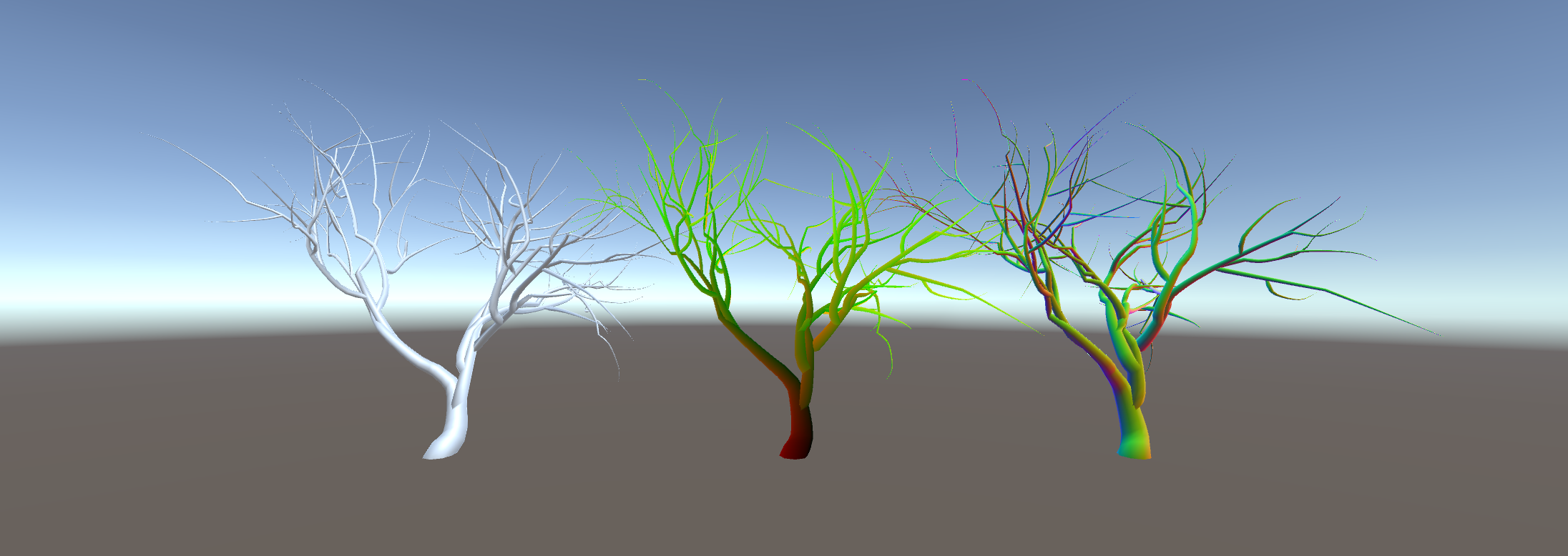
図1.16: ProceduralTree.scene
TreeData class
The TreeData class is a class that includes parameters that determine the degree of branching of branches and parameters that determine the size of the tree and the fineness of the mesh of the model. You can design a tree shape by adjusting the parameters of an instance of this class.
Branching
Use some parameters in the TreeData class to adjust the degree of branching.
branchesMin, branchesMax
The number of branches branching from one branch is adjusted by the branchesMin / branchesMax parameters. branchesMin represents the minimum number of branches, branchesMax represents the maximum number of branches, and the number between branchesMin and branchesMax is randomly selected to determine the number of branches.
growthAngleMin, growthAngleMax, growthAngleScale
The direction in which the branching branches grow is adjusted with the growthAngleMin and growthAngleMax parameters. GrowthAngleMin represents the minimum angle in the branching direction, and growthAngleMax represents the maximum angle. The number between growthAngleMin and growthAngleMax is randomly selected to determine the branching direction.
Each branch has a tangent vector that represents the direction of extension, and a normal vector and a binormal vector as vectors that are orthogonal to it.
The value randomly obtained from the growthAngleMin / growAngleMax parameters is rotated in the direction of the normal vector and the direction of the binormal vector with respect to the tangent vector in the direction extending from the branch point.
By applying a random rotation to the tangent vector in the direction extending from the branch point, the direction in which the branch at the branch destination grows is changed, and the branching is changed in a complicated manner.
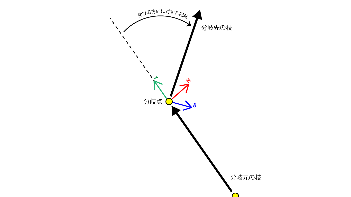
Figure 1.17: Random rotation applied in the direction extending from the branch point The T arrow at the branch point is the extending direction (tangent vector), the N arrow is the normal vector, and the B arrow is the normal line (normal vector). Binormal vector), and random rotation is applied in the direction of the normal and the normal with respect to the extending direction.
The growthAngleScale parameter is provided so that the angle of rotation randomly applied in the direction in which the branch grows increases toward the tip of the branch. This growthAngleScale parameter has a stronger effect on the rotation angle and increases the rotation angle as the generation parameter representing the generation of the branch instance approaches 0, that is, as it approaches the tip of the branch.
// The branching angle increases as the branch tip increases
var scale = Mathf.Lerp (
    1f,
    data.growthAngleScale,
    1f - 1f * generation / generations
);

// Rotation in the normal direction
var qn = Quaternion.AngleAxis(scale * data.GetRandomGrowthAngle(), normal);

// Rotation in the binormal direction
var qb = Quaternion.AngleAxis(scale * data.GetRandomGrowthAngle(), binormal);

// Determine the position of the branch tip while rotating qn * qb in the tangent direction where the branch tip is facing
this.to = from + (qn * qb) * tangent * length;
TreeBranch class
Branches are represented by the TreeBranch class.
If you call the constructor with TreeData for setting the branch pattern as an argument in addition to the parameters of the number of generations (generations) and the basic length (length) and thickness (radius), it will recursively internally. An instance of TreeBranch will be created.
A TreeBranch that branches from one TreeBranch is stored in a children variable of type List <TreeBranch> in the original TreeBranch so that all branches can be traced from the root TreeBranch.
TreeSegment class
Like Tubular, the model of one branch divides one curve, models the divided nodes as one Cylinder, and builds them so that they are connected.
The TreeSegment class is a class that expresses a clause that divides a single curve.
public class TreeSegment {
    public FrenetFrame Frame { get { return frame; } }
    public Vector3 Position { get { return position; } }
    public float Radius { get { return radius; } }

    // Direction vector tangent, which Tree Segment is facing,
    // FrenetFrame with vectors normal and binormal orthogonal to it
    FrenetFrame frame;

    // Position of Tree Segment
    Vector3 position;

    // Tree Segment width (radius)
    float radius;

    public TreeSegment(FrenetFrame frame, Vector3 position, float radius) {
        this.frame = frame;
        this.position = position;
        this.radius = radius;
    }
}
One TreeSegment has a FrenetFrame, which is a set of a vector in the direction in which the node is facing and an orthogonal vector, and variables that represent the position and width, and holds the necessary information at the top and bottom when building a Cylinder.
Procedural Tree model generation
The model generation logic of Procedural Tree is an application of Tubular, which generates a Tubular model from the array of Tree Segments of one branch Tree Branch and aggregates them into one model to form the whole tree. Modeling with an approach.
var root = new TreeBranch (
    generations,
    length,
    radius,
    data
);

var vertices = new List<Vector3>();
var normals = new List<Vector3>();
var tangents = new List<Vector4>();
var uvs = new List<Vector2>();
var triangles = new List<int>();

// Get the total length of the tree
// Divide the length of the branch by the total length to get the height of the uv coordinates (uv.y)
// Set to change from the root to the tip of the branch with [0.0 ~ 1.0]
float maxLength = TraverseMaxLength(root);

// Recursively follow all branches and generate a mesh corresponding to each branch
Traverse(root, (branch) => {
    var offset = vertices.Count;

    var vOffset = branch.Offset / maxLength;
    var vLength = branch.Length / maxLength;

    // Generate vertex data from a single branch
    for(int i = 0, n = branch.Segments.Count; i < n; i++) {
        var t = 1f * i / (n - 1);
        var v = vOffset + vLength * t;

        var segment = branch.Segments[i];
        var N = segment.Frame.Normal;
        var B = segment.Frame.Binormal;
        for(int j = 0; j <= data.radialSegments; j++) {
            // 0.0 ~ 2π
            var u = 1f * j / data.radialSegments;
            float rad = u * PI2;

            float cos = Mathf.Cos(rad), sin = Mathf.Sin(rad);
            var normal = (cos * N + sin * B).normalized;
            vertices.Add(segment.Position + segment.Radius * normal);
            normals.Add(normal);

            var tangent = segment.Frame.Tangent;
            tangents.Add(new Vector4(tangent.x, tangent.y, tangent.z, 0f));

            uvs.Add(new Vector2(u, v));
        }
    }

    // Build a one-branch triangle
    for (int j = 1; j <= data.heightSegments; j++) {
        for (int i = 1; i <= data.radialSegments; i++) {
            int a = (data.radialSegments + 1) * (j - 1) + (i - 1);
            int b = (data.radialSegments + 1) * j + (i - 1);
            int c = (data.radialSegments + 1) * j + i;
            int d = (data.radialSegments + 1) * (j - 1) + i;

            a += offset;
            b += offset;
            c += offset;
            d += offset;

            triangles.Add(a); triangles.Add(d); triangles.Add(b);
            triangles.Add(b); triangles.Add(d); triangles.Add(c);
        }
    }
});

var mesh = new Mesh ();
mesh.vertices = vertices.ToArray();
mesh.normals = normals.ToArray();
mesh.tangents = tangents.ToArray();
mesh.uv = uvs.ToArray();
mesh.triangles = triangles.ToArray();
mesh.RecalculateBounds();
Procedural modeling of plants is deep even with trees alone, and methods such as obtaining a model of a natural tree by branching so that the irradiation rate of sunlight is high have been devised.
If you are interested in modeling such plants, please refer to The Algorithmic Beauty of Plants * 6 , which was written by Aristid Lindenmayer, who invented the L-System, for various methods.
1.5 Application example of procedural modeling
From the procedural modeling examples introduced so far, we have learned the advantages of the technique of "dynamically generating a model while changing it according to parameters". You may get the impression that it is a technology for improving the efficiency of content development because you can efficiently create models of various variations.
However, like modeling tools and sculpting tools out there, procedural modeling techniques can also be applied to "interactively generate models in response to user input."
As an application example, we will introduce "Teddy," a technology that generates a three-dimensional model from contour lines created by handwritten sketches, devised by Takeo Igarashi of the Department of Computer Science, the University of Tokyo.
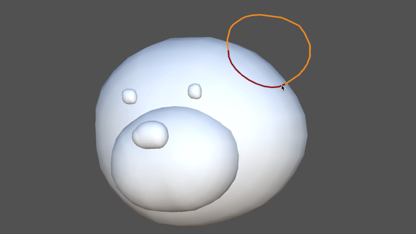
Figure 1.18: Unity assets of "Teddy", a technology for 3D modeling by hand-drawn sketches http://uniteddy.info/ja
This technology was actually used in the game "Junk Masterpiece Theater Rakugaki Kingdom" * 7, which was released as software for PlayStation 2 in 2002, and it is said that "the picture you drew is converted to 3D and moved as an in-game character". The application has been realized.
With this technology
- Define a line drawn on a two-dimensional plane as an outline
- A meshing process called Delaunay Triangulation * 8 is applied to the point array that constitutes the contour line.
- Apply the algorithm to inflate the mesh on the obtained 2D plane into a solid.
The 3D model is generated by the procedure. Regarding the details of the algorithm, a paper presented at SIGGRAPH, an international conference dealing with computer graphics, has been published. * 9
The version of Teddy ported to Unity is published in the Asset Store, so anyone can incorporate this technology into their content. *Ten
By using procedural modeling techniques in this way, it is possible to develop unique modeling tools and create content that develops according to the user's creation.
1.6 Summary
With procedural modeling techniques
- Streamlining model generation (under certain conditions)
- Development of tools and contents that interactively generate models according to user operations
I have seen that can be achieved.
Since Unity itself is a game engine, you can imagine its application in games and video content from the examples introduced in this chapter.
However, just as computer graphics technology itself has a wide range of applications, it can be considered that the range of applications for model generation technology is also wide. As I mentioned at the beginning, procedural modeling techniques are also used in the fields of architecture and product design, and with the development of digital fabrication such as 3D printer technology, there are opportunities to use the designed shapes in real life. Is also increasing at the individual level.
In this way, if you think about the fields in which you will use the designed shapes from a broad perspective, you may find various situations where you can apply procedural modeling techniques.
1.7 Reference
- CEDEC2008 Computer automatically generates content with intelligence --What is procedural technology?-Http://news.mynavi.jp/articles/2008/10/08/cedec03/
- The Algorithmic Beauty of Plants - http://algorithmicbotany.org/papers
- nervous system - http://n-e-r-v-o-u-s.com/